Headband controller
The joined rigid PCB contains the left and right headband mains, connected for assembly and testing before separation. The controller is an ESP32-S3-WROOM-1-N16R8, with USB-C current detection, two INA232 ear-feed monitors, ambient-light sensors and an LSM6DSV16BX motion/contact-audio sensor.
The current WROOM layout is routed. Cable continuity, loaded power and thermal behaviour, USB operation, audio and mechanical separation still need physical qualification. The temporary joined-test links are part of this saved PCB.
See the design reference, layout record, quote workflow and two-assembly carrier.
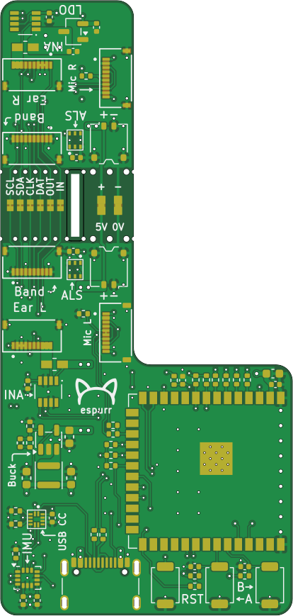
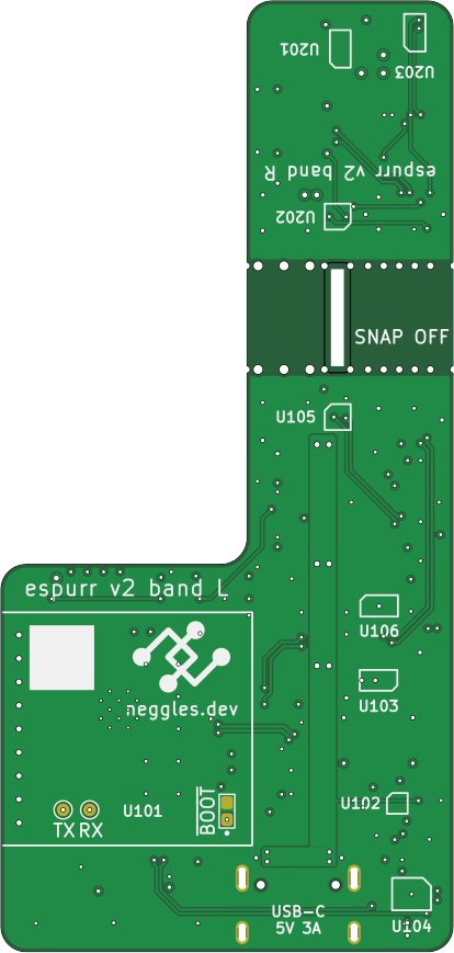
Schematics and assembly
- Schematic PDF — includes hierarchical sheets.
- Interactive BOM and board inspector.
- Component BOM (CSV).
- Exact saved PCB snapshot.
These are development documentation exports. The BOM is not a supplier upload file. Manufacturing packages and supplier acceptance are tracked by the board's build recipe.
Snapshot 2b1de97c7599 · Build manifest.